In this article there is a description how to make a modding control system using software. Under modding I mean coolers, diodes, neon and so on, that is all that work from electricity and that is your computer. I will make it through LTP1 port and with the help of Visual Basic 6.
Let’s begin, for this we’ll need:
- Printer cable (Tsetronics)
- A soldering iron and equipment to it.
- Modding tools;
First we’ll deal with hardware part of modding.
LTP1 port has 8 digital outputs and 5 inputs. Signal level is extended with maximum and minimum modes (0V-5V). Maximum resistance for outputs is 20 mA. If the resistance is higher you should use transistor or relay actuator. All outputs depend from each other.
LTP1 connector on the back of computer usually has 25 Sub-D contacts. Many printers have 36 contacts connector on the other end of the cable. Here's the position of the contacts in a connector:

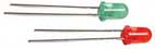
First try to make an easy scheme and test software on it. I’ve already said that maximum resistance for connector outputs is 20mA, it’s enough to connect a diode. Switch a diode in connector and don’t forget about resistor. The maximum output voltage is 5V, that’s why if you take 3V diode you’ll need 150 ohm resistor. Here’s the picture of this scheme

Diode could be changed with 12 V cooler or neon lamp. You'd better solder all this scheme on one board.
ATTENTION: You should never load output to more than 20 mA; otherwise some motherboards can damage or burn off.

Let’s deal with software; everything won’t work without it, because we don’t set any output to 5V voltage. For LTP1 there are no VB functions, the same as for controlling other things. There is an OUT [Adr.], [Wert], command in QBasic, that’s why it should be in VB. You'll need DLL file, input32.dll (there’s a link to this file below). I have made a small module for this and I can specify commands INP and OUT (like in QBasic) and control the connector.
Function.
'inpout32.bas'Inp and Out Deklarationen
Public Declare Function Inp Lib "inpout32.dll"Alias _
"Inp32" (ByVal PortAddress As Integer) As Integer
Public Declare Sub Out Lib "inpout32.dll"Alias "Out32" _
(ByVal PortAddress As Integer, ByVal Value As Integer)
Controlling the port:
Port address LTP1 - h378. You can search address in BIOS for more security. The following should be written there: LPT Adr : h378. The index shows the number from 0 to 255, by this number you can see whether there is someyhing connected to the port or not. We use here:
Output 1 = 1
Output 2 = 2
Output 3 = 4
Output 4 = 8
If the index is 0, none of the outputs have full 5V voltage. To use several outputs simultaneously you should put together all the figures.
For example:
Index = 1 | Output 1 = max., Outputs 2-8 = min.
Index = 3 | Output 1+2 = max., 1 + 2 = 3, Outputs 3-8 = min.
Index = 65 | Output 1+7 = max., 1 + 64 = 65, Outputs 2,3,4,5,6,8 = min.
And now if you want to switch on or off Output 1 in our example you should use the following code:
'Turn on:
Out &H378, 1
'Turn off:
Out &H378, 0
Files:
input32.dll
Sampler for all 8 outputs
Good modding everyone, SilentMods.com